- Signal Constellation
- A signal constellation is the physical diagram used to describe all the possible symbols used by a signalling system to transmit data and is an aid to designing better communications systems.
Why are constellation maps or diagrams useful?
They help you design a transmission system that is less prone to errors and can possibly recover from transmission problems without relying on higher level protocols. They also help you visually understand how a particular modulation mechanism works.
If you make a chart of all the possible values (symbols) that a modulation system can create during transmission, you end up with what is called a constellation map. When a communications device transmits, it modulates a pattern into the signal being transmitted. That pattern represents information and is called a symbol. Symbols are used to represent sets of zeroes and ones--binary data.
Between the transmission point and the receiption point, signals can get corrupted. A signal's original output power can be reduced or attenuated by the environment or the signal can get shifted out of phase. The signal can become so corrupted that it becomes unrecognizeable, unless the design of the transmission system and the modulation technique take this into account. Designing a modulation system that spreads the symbols apart in such a way that they are not easilly confused for one another is just part of designing a communications system.
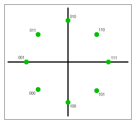
Both the selection of signal values and the selection of the bits those signal patterns represent are important to the design of the constellation map. The analysis of a transmission system's constellation map allows the development of error detection and error correction schemes that can detect transmission problems. Below is a constellation map for an eight symbol, three bit system. The green dots represent the values the signal should produce when transmitting the bit patterns showin in black text.

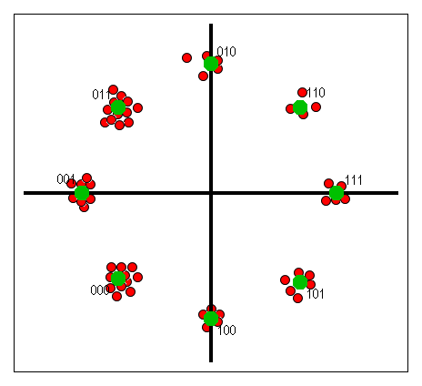
Here's what actually happens when the signal is transmitted. The red dots in the second diagram represent the value actually received. With this constellation arrangement, it is less likely that distortion or deterioration of the signal will result in a transmission error. Furthermore, it is possible for the receiver to detect errors and even correct them, if the transmission scheme is designed well enough. The red dots around the green dot labled 010 are automatically corrected to be the 010 value, because that is the symbol they most closely resemble. When a constellation is designed properly, it is not possible for one signal value to be confused with another.
