X.25 was one of the first digital communications protocols used in telephony and was developed in the 1970's by the telephone companies to provide data conectivity across their networks. X.25 is an International Telecommunication Union-Telecommunication Standardization Sector (ITU-T) document number specifying a WAN protocol of the same name. X.25 defines the interface between DTE and DCE over the public telephone network. The X.25 document specifies facilities for the Physical, Datalink, and Network layers of the OSI protocols for the X.25 protocol, but the term is most commonly used to refer to the Network layer functions of the protocol.
There are three categories of X.25 equipment:
|
Abbrev.
|
Name | Function |
|
DTE
|
Data Terminal Equipment | End station/system |
|
DCE
|
Data Circtuit-terminating Equipment |
Modems/Packet switches |
|
PSE
|
Packet Switching Exchange | Carrier Switches |
X.25 relies upon the Link Access Protocol Balanced (LAPB) protocol for transmission of data. X.25 frames are organized in two formats based on the size of the frame:
X.25 COMMUNICATION (An operational Example)
In X.25 communication two end stations (DTE devices) communicate by placing a call. This call is switched through the Public Switched Telephone Network (PSTN) via various PSE devices. As with a phone call, the receiving machine has the option to reject or accept the call. When a call is successfully established, full-duplex communication is initiated. Both the 'caller' and the 'receiver' can terminate the call at any time.
X.25 is a reliable protocol utilizing virtual circuits between two communicating terminals (DTE devices). X.25 virtual circuits are can be considered an end to end connection where the internal switches of the PSTN are transparent to the call. Multiple virtual connections can be multiplexed over a single physical connection, thus making it a more efficient use of available cable and bandwidth. This was one of the reasons for the protocol's development.
Individual calls are multiplexed together, switched accross the PSTN and later demultiplexed at the destination. X.25 supports both permanent and switched virtual circuits.
Permanant Virtual Circuits (PVC's) are mapped by humans across the network and do not change over time. Typically, these types of circuits are used to wire together a dedicated path from point to point.
Switched Virtual Circuits (SVC's) are set up and torn down dynamically by the connecting equipment. These circuits are used to create a mesh of circuits to allow the switching of multiple calls across a single network simultaneously.
X.25 PROTOCOL SUITE
| OSI Layers | X.25 Protocol Suite |
| Network | PLP |
| Data Link | LAPB |
| Physical | X.21bis EIA/TIA-232 EIA/TIA-449 EIA-530 G.703 |
- PLP
- Packet-Layer Protocol - Handles call setup, data transfer, idle tracking, call clearing and restarting. PLP manages the exchange of information between two DTE stations across virtual circuits. PLP can also run over LLC2 and ISDN interfaces running Link Access Procedure (LAPD) on the D channel.
| MODE | Description | Executed | Used With |
| Call Setup |
Call setup is managed by PLP between two DTE stations using the X.121 addressing scheme to set up the virtual circuit. Each call is independent of other calls, so calls can be in various stages and not affect one another. Call Setup is only done with SVC's, as PVC's are already connected after they are built. | Per Circuit | SVC's |
| Data Transfer |
As the name states, data transfer is handled by PLP between two DTE stations across an SVC or PVC. Since data is transmitted in a constant stream, when there is no data the channel is padded with zeroes. Padding, segmentation and reassembly, error and flow control are handled | Per Circuit | SVC's & PVC's |
| Idle | Intermediate mode between connection and data transfer mode. | Per Circuit | SVC's |
| Call-Clear | Used to tear down a virtual circuit and end a call between DTE stations. | Per Circuit | PVC's & SVC's |
| Restarting | Transmission synchronization between two DTE devices. This is used prior to entering Data Transfer Mode and to re-establish synchronization is lost. | Per DTE Device |
PLP Packet Type Fields:
General Format Identifier (GFI) -- Identifies the packet's parameters such as whether the packet contains Data or Control information, type of windowing performed, and whether to use Delivery Confirmation.
Logical Channel Identifier (LCI) -- Identifies the local virtual circuit.
Packet Type Identifier (PTI) -- Identifies one of the following packet types:
| CALL ACC | Call Accept |
| CALL REQ | Call Request |
| CLR CNF | Clear Confirmation |
| CLR REQ | Clear Request |
| DATA | Data Packet |
| DIAG | Diagnostic |
| INT CNF | Interrupt Confirmation |
| INT REQ | Interrupt Request |
| REJ | Reject |
| RES CNF | Reset Confirmation |
| RES REQ | Reset Request |
| RNR | Receive Not Ready |
| RR | Receive Ready |
| RSTR CNF | Restart Confirmation |
| RSTR REQ | Restart Request |
| REG REQ | Registration Request |
| REG CNF | Registration Confirmation |
User Data -- Encapsulated data from upper-layer. Only present in Data Packets, otherwise this field is used for additional control fields.
- LAPB
- Link Access Procedure, Balanced (LAPB) -- Manages packet framing between DTE and DCE stations. LAPB is capable of placing frames in the correct order, as well as checking packets for errors (error detection).
| LAPB Frame types | |
| Information (I-Frame) |
Carries upper layer information ans some control information. Includes sequencing, flow control, error detection, and recovery. |
| Supervisory (S-Frame) |
Carries control information. Used to request and suspend transmission, report status, and Ack. receipt of I-Frames. |
| Unnumbered (U-Frame) |
Used for Link setup, and disconnection, error reporting. No sequence numbers used. |
-
- Additional Notes:
- X.21bis
X.21bis is a physical-layer protocol used in X.25 that defines the electrical and mechanical procedures for using the physical medium. The physical X.25 connector is 15 pins with some pins used as NULL (unconnected). Please refer to the chart below:
| PIN/WIRE | NAME | From DTE |
From DCE |
| G | GROUND | - | - |
| Ga | DTE common ground | Y | |
| T | Transmit | Y | |
| R | Receive | Y | |
| C | Control | Y | |
| I | Indication | Y | |
| S | Signal Element Timing | Y | |
| B | Byte Timing | Y |
DTE INTERFACE
The DTE uses the Tx and Ctrl circuits to transmit data and
control information, and the common ground for electrical purposes.
DCE INTERFACE
The DCE uses the Rx and Indication circuits for data and control. The DCE emits a timing signal stream on S to indicate bit-level timing to the DTE end. The DCE can also use the B wire to indicate byte-level framing. If the B circuit isn't used, two synchronization bytes (SYN) are transmitted from DCE to DTE to allow the DTE to synchronize and calculate the byte-frame boundary.
As explained above, X.21bis handles the activation and deactivation of the physical medium connecting DTE and DCE devices. It supports point-to-point connections, speeds up to 19.2 kbps, and synchronous, full-duplex transmission over four-wire media. (See below).
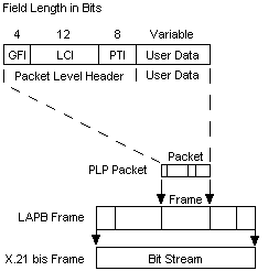
LAPB Frame Format
LAPB frames include a header, encapsulated data, and a trailer. Figure 17-6 illustrates the format of the LAPB frame and its relationship to the PLP packet and the X.21bis frame. The following descriptions summarize these fields:
| Frame Fields (Frame structure) | |
| Flag | Delimits the beginning the end of the LAPB frame. Bit stuffing is used to ensure that the flag pattern does not occur within the body of the frame. |
| Address | Indicates whether the frame carries a command or a response. |
| Control | Qualifies command and response frames and indicates whether the frame is an I-frame, an S-frame, or a U-frame. In addition, this field contains the frame's sequence number and its function (for example, whether receiver-ready or disconnect). Control frames vary in length depending on the frame type. |
| Data | Contains upper-layer data in the form of an encapsulated PLP packet. |
| FCS | Handles error checking and ensures the integrity of the transmitted data. |
X.121 Address Format
The CCITT document X.121 defines an addressing scheme for phone numbers that is also used for X.25. All X.25 packets begin with a 3 byte header composed of a group, channel and type field. The GROUP byte always begins with the sequence 0001. The GROUP and CHANNEL bytes are there to provide a 12 bit field for the X.121 address.
X.121 addresses are used by the X.25 PLP in call-setup mode to establish SVCs. The X.121 address includes an IDN field. The X.121 Address field includes the International Data Number (IDN), which consists of two fields: the Data Network Identification Code (DNIC) and the National Terminal Number (NTN). DNIC is an optional field that identifies the exact PSN in which the destination DTE device is located. This field is sometimes omitted in calls within the same PSN. The DNIC has two subfields: Country and PSN. The Country subfield specifies the country in which the destination PSN is located. The PSN field specifies the exact PSN in which the destination DTE device is located. The NTN identifies the exact DTE device in the PSN for which a packet is destined. This field varies in length.
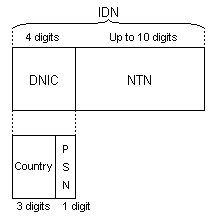
The X.121 Address field includes the International Data Number (IDN), which consists of two fields: the Data Network Identification Code (DNIC) and the National Terminal Number (NTN). DNIC is an optional field that identifies the exact PSN in which the destination DTE device is located. This field is sometimes omitted in calls within the same PSN. The DNIC has two subfields: Country and PSN. The Country subfield specifies the country in which the destination PSN is located. The PSN field specifies the exact PSN in which the destination DTE device is located. The NTN identifies the exact DTE device in the PSN for which a packet is destined. This field varies in length.